Instrumentation of centrifuge systems explained for laboratory users

What centrifuge instrumentation actually controls
The instrumentation of centrifuge systems is the set of sensors, controls, displays, interlocks, and verification points that manages a centrifuge run. It does more than start and stop a motor. It converts a method requirement into controlled rotor speed, relative centrifugal force, run time, acceleration, braking, temperature, imbalance response, lid locking, and rotor protection. For laboratory users, the value is practical: good instrumentation makes separations more repeatable, keeps sample conditions closer to the method, and reduces the chance that an operator error becomes a safety event.
A centrifuge is mechanically simple in principle. Beckman Coulter’s educational material describes the core machine as a rotor, drive shaft, and motor, usually enclosed in a cabinet that supports the system and helps protect the operator. The instrumentation layer is what makes that mechanical system suitable for modern biological, clinical, pharmaceutical, and analytical workflows. For more background on related measurement systems, see our core instrumentation section.
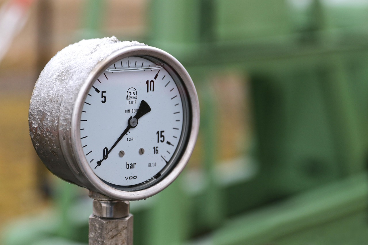
The measurement layer behind speed, RCF, time, and temperature
Most centrifuge methods appear to require only a few settings, but each setting depends on an instrumented feedback loop. The operator may enter RPM, RCF, time, temperature, acceleration, or braking level. Internally, the centrifuge has to measure motion, compare it with the set point, and correct deviations through the drive and control electronics.
RPM and RCF are related but not interchangeable
Rotational speed is usually displayed as revolutions per minute, or RPM. Separation force is better described as relative centrifugal force, or RCF, often expressed as multiples of gravity. The two are connected by rotor radius. A common calculation is RCF = 1.118 × 10^-5 × r × RPM^2, where r is the rotational radius in centimeters. Because radius changes with rotor design and sample position, the same RPM can produce different RCF values in different rotors.
This is why centrifuge instrumentation should not be treated as a generic speed dial. A method written only as RPM may be difficult to reproduce on another rotor. A method written as RCF is usually more transferable, provided that the centrifuge or the user applies the correct radius. Instruments with built-in RPM to RCF conversion reduce manual calculation errors, but the rotor data still has to be correct.
Timing and braking affect the actual separation
The timer is not just a convenience feature. Short spins, pelleting steps, blood processing, wash steps, and density-gradient separations can all be sensitive to the time spent at operating speed. Some instruments count from the moment the run starts; others may offer timing only after the set speed is reached. Users should check the manual when a method is sensitive to ramp time.
Braking is another controlled variable. A strong brake shortens turnaround time, but it may disturb loose pellets or interfaces. A gentler brake can preserve separation quality, although it extends the run. Instrumentation that allows selectable acceleration and deceleration profiles gives users more control than a single fixed stop behavior.
Temperature control matters beyond refrigerated models
Refrigerated centrifuges use temperature probes, control boards, compressors or other cooling technologies, fans, and chamber design to keep samples near the selected temperature. The display may show a chamber value rather than the exact sample temperature, so demanding protocols often require qualification under realistic rotor, load, and run conditions. Even non-refrigerated centrifuges can warm samples during high-speed operation because motor heat and air friction increase during the run.
Safety interlocks are part of the instrumentation, not accessories
Modern centrifuge safety depends on instrumented protection as well as operator training. Lid locks help prevent opening while the rotor is moving. Imbalance detection can decelerate or stop the run when vibration exceeds a defined threshold. Overspeed protection and rotor recognition can prevent a rotor from being driven beyond its rated limit. These functions do not replace correct loading, but they reduce the consequences of some foreseeable errors.
Eppendorf’s centrifuge safety guidance notes that many larger benchtop, floor-standing, and ultracentrifuge models include automatic imbalance detection that can decelerate or shut down the system when excessive imbalance is detected. The same guidance is clear about an important limitation: imbalance detection does not automatically compensate for an unbalanced load. The user still has to stop, unload, inspect, and correctly balance the rotor.
Rotor recognition is another important safeguard. In multipurpose centrifuges, the same drive can accept different rotors with different maximum speeds and load limits. Automatic rotor recognition helps the instrument limit RPM or RCF to the installed rotor’s permitted value. Where rotor recognition is not available, laboratories depend more heavily on method control, labeling, training, and manual checks.
Biosafety adds another layer. CDC laboratory safety guidance emphasizes documented instructions for each centrifuge type, including startup, shutdown, emergency procedures, balancing, safety cups and covers, rotor and container selection, high-speed or ultracentrifuge requirements, and fill-height limits. The CDC also warns that tube breakage during centrifugation can generate aerosols, which is why sealed rotors, gasketed safety cups, and opening containment procedures matter when handling infectious or potentially hazardous materials.
A practical map of centrifuge instruments, signals, and failure modes
The table below summarizes how common centrifuge instrumentation connects to laboratory decisions. It is not a replacement for a manufacturer manual, but it helps users identify which measurement or control point is tied to each risk.
| Instrumented function | What it monitors or controls | Why it matters | Common user check |
|---|---|---|---|
| Speed measurement | Rotor RPM through a tachometer, encoder, or motor feedback | Determines the actual centrifugal field and separation outcome | Verify method settings and calibrate speed at defined intervals |
| RCF calculation | Converts RPM using rotor radius | Makes protocols more comparable across rotors | Confirm the correct rotor is selected or recognized |
| Timer | Run duration and, on some models, time at set speed | Affects pellet formation, wash efficiency, and process consistency | Check whether timing starts at run start or at set speed |
| Temperature control | Chamber or rotor-area temperature in refrigerated models | Protects temperature-sensitive samples and reagents | Pre-cool when required and verify temperature for critical methods |
| Imbalance detection | Vibration or uneven loading response | Reduces risk of rotor damage, instrument movement, or crash | Balance by mass, load symmetrically, and stop if vibration is abnormal |
| Lid lock | Door closure and rotor motion state | Prevents access to moving parts during operation | Do not bypass interlocks or force the lid |
| Rotor recognition | Installed rotor identity or permitted operating range | Helps prevent overspeed operation | Inspect rotor ID, adapters, buckets, and maximum ratings |
| Service diagnostics | Error codes, run history, and internal checks | Supports troubleshooting and preventive maintenance | Record recurring errors and remove suspect instruments from use |
Calibration and verification for controlled workflows
Centrifuge calibration usually focuses on the parameters the instrument claims to control: rotational speed, time, and temperature where applicable. Commercial ISO/IEC 17025 calibration providers commonly verify RPM with traceable tachometers, timer performance with calibrated timing references, and temperature with traceable temperature probes or loggers. A comprehensive service visit may also include rotor inspection, as-found data, as-left data, uncertainty statements, and documentation of environmental conditions.
The right interval depends on the laboratory’s quality system, risk assessment, workload, and regulatory environment. A teaching lab may set a different verification schedule from a GMP production lab, a clinical specimen processing unit, or a blood bank. The underlying logic should be the same: if a method depends on a centrifuge value, the lab needs evidence that the value is reasonably accurate and that deviations are handled. See also: analytical methods.
Calibration records are especially important when results must be defended during audits, method transfers, investigations, or instrument replacement. A run that appears routine can become difficult to interpret if the lab cannot show that RPM, time, and temperature were within acceptable limits. For refrigerated centrifuges, temperature verification should be performed under conditions that resemble actual use whenever sample temperature is critical.
The 2026 standards and compliance context
Safety standards are not operating manuals, but they strongly influence centrifuge design. The International Electrotechnical Commission published IEC 61010-2-020:2026 on September 2, 2026. The IEC describes it as the fourth edition of the particular safety requirements for electrically powered laboratory centrifuges, replacing the 2016 edition and aligning with changes in IEC 61010-1. This matters because centrifuge instrumentation is closely tied to safety functions such as containment, moving-part protection, and fault response.
In the United States, refrigerated centrifuges also appeared in a 2026 environmental compliance discussion. In a Federal Register final rule published on May 26, 2026, the U.S. Environmental Protection Agency extended the compliance date to January 1, 2028, for refrigerated laboratory centrifuges and refrigerated laboratory shakers within the industrial process refrigeration subsector. The EPA explained that the extension gives time for standards and equipment updates related to safe deployment of new refrigerants in this niche application.
For buyers and laboratory managers, the point is not that every centrifuge suddenly needs replacement. The direction is clear, however: instrumentation, safety testing, refrigerant selection, and documentation are becoming more connected. When comparing new refrigerated models, users should ask not only about maximum RPM and capacity, but also about rotor recognition, imbalance response, temperature validation, service documentation, applicable safety listings, and refrigerant compliance timing.
How to evaluate centrifuge instrumentation before purchase or use
A centrifuge specification sheet can look impressive while still leaving important instrumentation questions unanswered. The following checklist helps translate technical features into laboratory decisions.
- Match RCF, not only RPM. Confirm that the centrifuge and rotor can deliver the required RCF at the sample position used by the method.
- Check rotor compatibility. Review maximum speed, maximum load, adapter requirements, bucket limits, tube fit, and aerosol-tight options.
- Review safety interlocks. Look for lid locking, imbalance detection, overspeed protection, rotor recognition, and clear fault messages.
- Define temperature expectations. For refrigerated runs, ask whether the displayed value represents chamber, air, rotor, or a control sensor position.
- Understand timing logic. Determine whether the timer starts immediately or at set speed, especially for short or sensitive separations.
- Plan calibration access. Ensure that RPM, timer, and temperature can be verified without unsafe modifications or unclear procedures.
- Consider documentation quality. Manuals, service records, rotor life limits, and maintenance logs are part of the usable instrument system.
For daily users, the most important habit is to treat warnings as data. A repeated imbalance message, unusual noise, slower acceleration, temperature drift, or lid-lock error may indicate a real mechanical or electronic issue. Continuing to run through symptoms can turn a small service problem into a safety or sample integrity problem.
Frequently asked questions
Is centrifuge instrumentation the same as centrifuge calibration?
No. Instrumentation is the built-in measurement and control system of the centrifuge. Calibration is the external verification that selected instrument readings, such as RPM, time, and temperature, match traceable reference standards within defined tolerances.
Why do protocols often prefer RCF over RPM?
RCF accounts for rotor radius, while RPM only states rotational speed. Because two rotors can produce different centrifugal force at the same RPM, RCF is usually more meaningful when transferring a protocol between instruments.
Can imbalance detection make balancing unnecessary?
No. Imbalance detection is a protective feature, not an automatic balancing system. Users still need to balance tubes by mass, load rotors symmetrically, use correct buckets and adapters, and stop the run if vibration becomes abnormal.
What should be calibrated on a refrigerated centrifuge?
The usual verification points are speed, timer accuracy, and temperature. For critical methods, temperature checks should reflect actual operating conditions, including rotor type, load, set point, and run duration.
What is the main purchasing lesson from centrifuge instrumentation?
Do not compare centrifuges only by maximum speed or tube capacity. The more important question is whether the instrument can control and document the conditions your method depends on, while providing appropriate safety interlocks for the samples and rotors you use.